


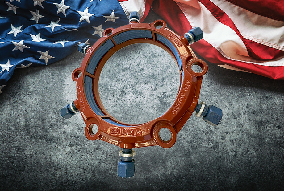
Series 2300 Mechanical Joint Restraint for C909/PVCO Pipe
If a restraint is not developed and designed with a specific purpose and for a particular pipe, how can you expect it to have optimal performance? At EBAA Iron, we keep this in mind while designing and developing new products.
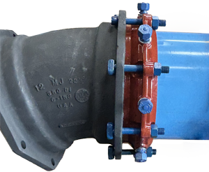
The Series 2300 PVCO/C909 mechanical joint restraint was designed and developed from the outset to be a restraint for PVCO pipe. Based on EBAA’s research and development testing, EBAA is aware that C909 pipe restraints require a unique approach to grip the PVCO pipe properly. The 2300 restraint uses a wider, longer, and radius-matched series of wedges that provide nearly 360º circumferential grip on the pipe. The 2300 design contains pipe wall deflection, imparts no point loading, and eliminates shear points, all while providing the proven MEGALUG® ease of installation.
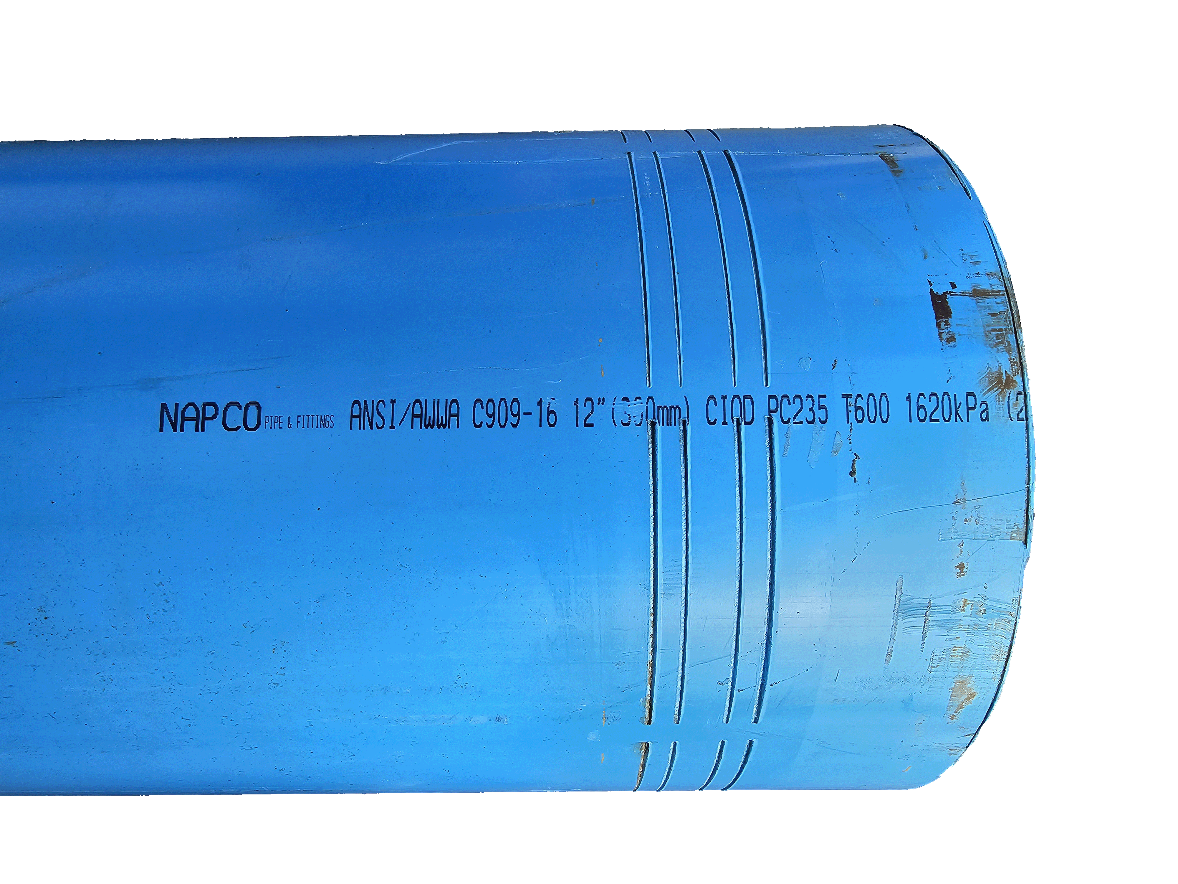
PVCO pipe is manufactured by batch or continuous process. Batch process manufacturing starts with a stock of pipe that is approximately ½ the diameter and 2x the thickness. The pipe is then loaded into a mold, heated, and expanded by internal pressure. The 2nd process is a continuous process, where the original, approximately ½ the diameter, and 2x the thickness stock is pulled and stretched over a mandrel. Each process results in PVCO pipe, which is thinner than equivalent pressure-rated C900, and the polymer chains are oriented in the hoop direction. The manufacturing process for C909 pipe has evolved, necessitating the development of pipe restraints for C909 to keep pace. The manufacturing process creates a pipe that is thinner and lighter, and reacts differently to joint restraints compared to C900 PVC
EBAA recognized the challenges of gripping and restraining the thinner-walled molecularly oriented C909 pipe and set out to design a restraint that meets EBAA’s industry-leading restraint performance standards. The 2300 series restraint has proven to meet EBAA’s performance standard and passed all EBAA’s rigorous design testing.
 |
 |
Since introducing its first patented product in 1968, EBAA has continued to lead the way in innovative products for the water and wastewater industry that are engineered to save time and money. EBAA is the only manufacturer of the world famous MEGALUG® Mechanical Joint Restraint. EBAA specializes in water and waste-water pipeline joints and is 100% MADE IN THE USA.